The old power supply circuit, the drive motor speed control circuit, and the directional control circuit still work. They are now connected to my laptop via the Phidget 8/8/8 (see below) and I have written new speed control and direction control software in C. Rather than only 10 speeds, Mike now has 200 speeds (100 forward and 100 reverse), for finer control.
I had considered replacing the drive motor speed control with a new DC motor controller, which would have handled the drive signal pulsing in firmware and also provided valuable signal feedback, but I ultimately decided to keep the legacy boards in place where possible. This means that I wrote my own speed functions, delivering from 0 to 100 pulses to the drive motors every 100 microseconds. Fun to do and I’m glad that it works. Down the road, however, this circuit may have to be upgraded or replaced: The legacy speed control circuit delivers the same signal to all drive motors, which are wired in parallel. Separate speed control of each individual drive motor is not possible and Mike’s geometry calls for this feature.
The directional control appeared at first to not function, but it turned out that the drive current was being limited by too great a factor. Probably because my Microtron is powered by a motorcycle gell cell instead of the original old-style liquid acid car battery that Todd’s Mike used. The 4.7 Ohm 10 Watt resistor (limiting the drive current) will need to be replaced with one of smaller value. But like the speed control circuit, the “proper” step in this case would be to use a full-blown motor controller.

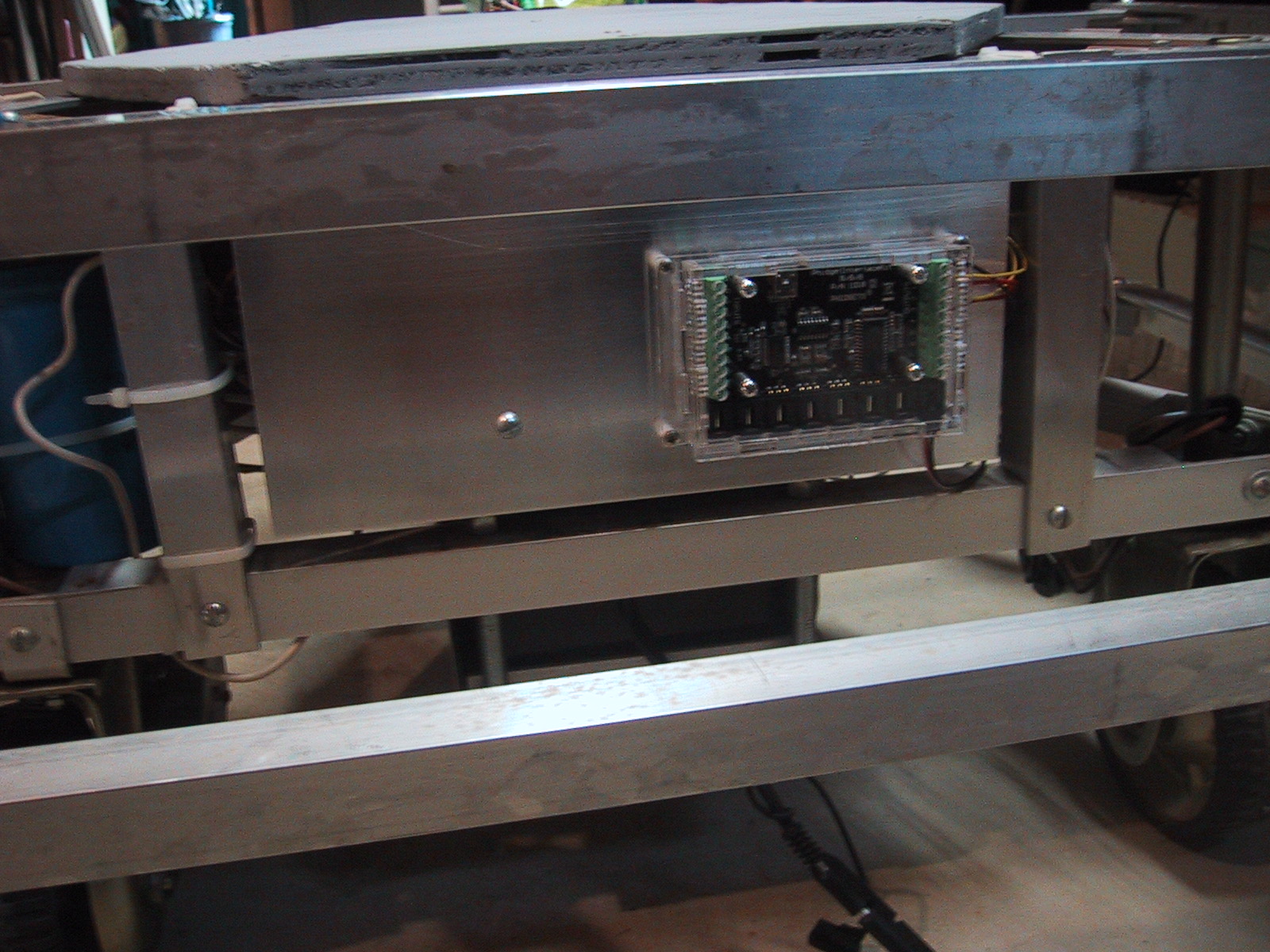
Phidget 8/8/8 mounted on Microtron Robot, in former location of the directional control circuit. The new aluminum sheet on which it is mounted matches Mike's classic 1980s appearance. Visible at the bottom of the photo are part of the battery cage and the new battery charging cable.
All that remains for Mike to be somewhat autonomous is the addition of sensors. Probably fixing the impact sensors (ie, bumpers) and/or adding the ultrasonic detector will be next. Then transferring Mike’s new “brain” from my laptop to some sort of on-board SBC.

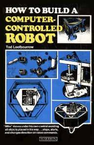
 "How to build a computer-controlled robot" (amazon)
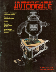
 1977 Interface Age Article (pdf)