The Directional Control Potentiometer has been attached to the front wheel using the same dowel method described by Tod. Instead of a screw, however, I used super-glue to hold the dowel in place. I also had to add a small block of wood (held on with Elmer’s glue) beneath the aluminum mounting bracket.
Archives
All posts by site owner
Completed the directional control circuit. Tod has his relays mounted on the circuit board, mine are instead attached to the support bracket immediately to the left of the circuit (not visible in photo). Visible on the top right is the emergency shut-off switch for the speed control circuit.
The directional control circuit is mounted on the rear side of the triangle frame.
Completed the battery cage, altered from Tod’s measurements to fit a pair of 6v gel cells (in series).
Completed construction and assembly of the upper triangle portion of Microtron’s frame.
Completed cutting and assembling the lower triangle portion of Microtron’s frame.
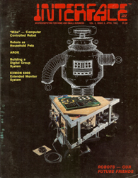
In the summer of 1976, a bright young teenager named Tod Loofbourrow built a 70 pound motorized mobile robot which he dubbed “Microtron” (or “Mike” for short). His robot was controlled by the KIM-1 computer, was built out of angle aluminum and plywood, was powered by an 84-amp car battery, and could carry a load of 600 pounds. Both he and an early version of his ‘bot were written-up in the April, 1977 issue of Interface Age magazine.
(A PDF scan of that article is available here.)
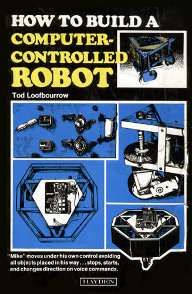
Tod continued to develop the robot, and at the age of 16, he was approached by Hayden Publishing to write a book about it. In 1978, How to Build a Computer Controlled Robot was published:
Tod moved on to other things, but many hobby roboticists in the late 70s through the 1980s built their own Microtron robots using his book. This website is about one of them. (There are some other Microtron Robots linked to from this site’s right-hand navigation bar.)


 "How to build a computer-controlled robot" (amazon)